01
High-power RF systems
Custom RF amplifiers, generators and HF power chains for demanding duty cycles.

RF engineering · prototyping · production
High-power RF product development for equipment manufacturers and engineering teams—from a new design or difficult prototype to validated, production-ready hardware.
What we build
High-power RF only works when the signal path, control logic, mechanics and thermal design are developed together.
Custom RF amplifiers, generators and HF power chains for demanding duty cycles.
Low-loss combiners, couplers and low-pass filters designed for the complete system.
MCU firmware, monitoring and protection for dependable RF operation.
Electrical, thermal and mechanical design through enclosure integration and production transfer.
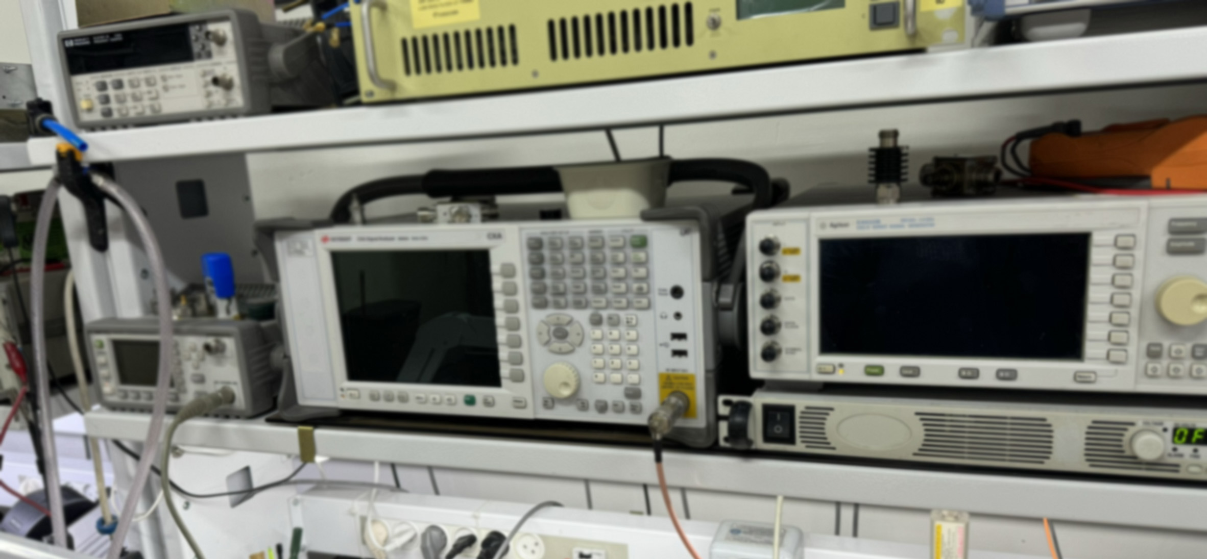
Inside the lab
Assembly and measurement sit beside the design team, turning every test into the next engineering decision.
In-house SMT assembly, fixtures and enclosures.
RF characterization, fault analysis and documented checks.
Rated loads for stress and endurance testing.
RF models and embedded control tools.
Engineering tools
Calculate an ideal match or size a half-wave dipole. Switch to Explore to see how matching and resonance behave.
Your load. A matching network. Clear component values.
Build from load → source
Ideal values at one frequency. Verify on real hardware.
Assumes the entered load at that frequency; values are rounded. Excludes losses, parasitics, bandwidth and power ratings. Matching principles ↗
Half-wave dipole dimensions and resonance, up to 1 GHz.
First-resonance estimate. Verify and trim on real hardware.
L = k × c / (2f), for a straight, centre-fed dipole; k defaults to 0.95. Excludes wire diameter, insulation, height, surroundings and feed-line effects. At UHF, small dimensional and feed-point changes matter. Animation is illustrative, not a field simulation. Dipole principles ↗
How we work
Five stages, with a clear deliverable at each handoff.
Requirements, interfaces and real operating conditions.
Requirements mapRF, electronic, mechanical and embedded design.
Design reviewRapid prototypes and in-house SMT assembly.
Working prototypeMeasurement and high-power testing up to 40 kW.
Test evidenceSource files, documentation and engineering support.
Source packageA technical conversation starts here
Tell us about the application and the RF challenge. Share only what you’re comfortable disclosing.
Email Tugicom